Every day, thousands of signmakers work, in some fashion, with neon transformers. During the last 15 years, I’ve become a cheerleader for what I view as the MVP of the electric-sign league. I believe its value is unparalleled.
However, transformers remain the "Rodney Dangerfield" of sign components. They’re heavy and bulky, plus they often have that "industrial-grunge" look. Transformers don’t present a pretty face.
Underneath that grey, black or white exterior resides major-league technology. This article will provide a close look at how this electric-sign staple is designed, how it functions and how it fails.
Purpose and function
What is a transformer? Encyclopedia.com states:
"A transformer is an electrical device used to transfer an alternating current or voltage from one electric circuit to another by means of electromagnetic induction. The simplest type of transformer consists of two coils of wire, electrically insulated from one another and arranged so that a change in the current in one coil (the primary) will produce a change in voltage in the other (the secondary)."
As an electrical device, a neon transformer serves two functions. First, it provides the start-up voltage necessary to strike the arc that begins the tube-lighting process. Because generating light requires very high voltage to excite the gas molecules inside a tube, the device must "step up" the voltage available from the incoming electric supply line.
This is the "transforming" task of the device. The voltage of a typical U.S. supply line is 120 or 277 volts. The transformer bumps this between 500V and 7,500V, depending on the size, gas fill and number of tubes to be illuminated.
Additionally, the neon transformer limits and controls voltage and current, which occur in the tube after the arc is started. Because neon tubes are a "gas-discharge, negative-resistance" type of lighting, they would be destroyed if high voltage and current were continuously applied.
By limiting and controlling power, a transformer actually performs a ballasting function. Later, we’ll explore how transformers are designed and manufactured to effectively perform these jobs, but first, let’s look at how they actually work.
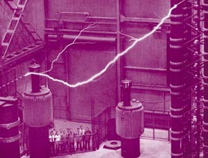
It’s almost magic
Before recorded history, magnetism and electricity had mystical associations. The ancient Greeks and Chinese worked magnetism into both fable and everyday practice. According to legend, the Chinese first used a magnetic compass, eventually transmitting the idea to the Arabs, who brought it to Europe.
During the Enlightenment of the late 17th and 18th centuries, much research and experimentation focused on electricity and magnetism, culminating with the work of English physicist Michael Faraday, who "discovered" electromagnetic induction. His work made neon transformers possible.
Faraday found that current could be induced from one copper coil to another by moving a magnet through them. Each time he moved the magnet, current would be induced briefly in one of the coils. He also found electricity could be generated in a wire coil by means of the electromagnetic effect created when a current is applied to another wire coil. If only Faraday could have seen what magic came from his discoveries — all of our modern-day electrical generators, motors and transformers are derived from his work.
Another great electromagnetic researcher, Nicola Tesla, completed his magic act a half century later. His work on rotating magnetic fields led to the development of the induction motor and the concept of alternating current (AC).
George Westinghouse bought patent rights to Tesla’s devices in 1885, and ultimately commercialized them to bring us today’s AC power grid. By using AC, neither the transformer’s coils nor magnet must be moved in order to make things work; switching the current back and forth does the trick.
Design and fabrication
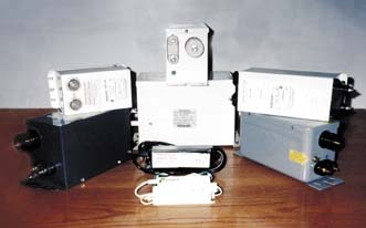
Today’s neon transformer falls into one of three functional design categories: ferromagnetic, solid-state or hybrid. Ferromagnetic transformers combine copper coils and a magnetic steel core to generate the desired current and voltage. All that metal accounts for its unwieldy size and weight.
Conversely, when compact size and lighter weight are desired, a transformer built with electronic components offers an alternative. With advances in solid-state technology, combinations of metal-oxide semiconductor field-effect transmitters (MOSFETs), rectifiers, filters, diodes, etc., can be used to create an effective, economical design. These units produce a high-frequency waveform output of approximately 20,000 Hertz.
For some applications, a hybrid is most appropriate. These designs feature a core-and-coil (c-n-c) assembly, albeit much smaller than conventional units. The c-n-c links with certain solid-state components to create a transformer more powerful than smaller solid states and not as bulky as ferromagnetics.
The heart of the conventional ferromagnetic transformer is the c-n-c assembly. Each transformer design has a primary coil and at least one secondary coil. Most neon transformer designs have two secondary coils (for reasons to be explained later). A coil comprises windings of a special grade of copper wire pre-coated with an insulating finish. It’s called either "magnet" or "magnetic" wire.
Magnet wire is a solid copper conductor with a larger diameter for the primary coils and a smaller diameter for the secondary coils. The ratio of the wire’s turns on the primary coil to those on the secondary coil determines the transformer’s output.
Typically, magnet wire is also specified because it withstands high temperatures generated by these magnetic inductance devices. Ultimately, careful selection of magnet wire determines the transformer’s performance life. So, reputable transformer manufacturers choose very carefully.
The coils may be either bobbin wound or "layer wound," in which copper winding is interspersed with insulation layers. The bobbin-wound coils are more compact, accurate and lighter, but they may be more expensive. For insulation, manufacturers typically use a form of thin tape, rather than paper, as in the layer-wound coils.
The assembly’s core comprises layers of thin, magnetic, steel sheeting pre-cut into shapes. The cut-out areas in the steel lamination are carefully designed and precisely controlled. Upon final assembly, lamination stacks must fit closely within a certain tolerance around and through the coils of copper wire. Lack of these tolerances may cause premature breakdown of the transformer.
The shunt also impacts neon-transformer performance. Like the core, the shunt is a stack of magnetic steel laminations, although of much smaller geometry. It bypasses or diverts magnetic flux that could otherwise be drawn as current by a secondary load. The shunt’s design and size limits this current so the transformer operates within normal parameters.
To summarize, by assembling a c-n-l, shunts and appropriate hardware for making wiring connections, we have a working transformer.
Design a proper enclosure
One form of enclosure would be the sign itself. In certain custom applications, this can be done effectively and safely. However, a sign fabricator typically purchases an encased transformer. In North American markets, most sign companies use units featuring metal cases fabricated and assembled within the transformer manufacturer’s facility. The resulting transformer is relatively compact, economical and safe. The metal case offers physical protection for the c-n-c assembly, as well as a framework to which wires, insulators, terminals, switches, etc., can be securely attached.
The case’s metal also must be carefully specified. It must withstand the physical requirements of its purpose to provide years of water-resistant protection in damp locations. More often than not, these demands call for galvanized steel, although aluminum is sometimes used. Also, the selected metal must be capable of being fabricated into a container for the final ingredient: fill material.
As expected, putting a metal enclosure around a high-voltage transformer introduces problems. Most prevalent is the arc potential from coil to case. A case large enough to provide spacing that prevents such an arc is impractical. It would be very bulky and create a nice little oven in which to bake the c-n-c. The heat generated by the assembly couldn’t effectively escape from the enclosure. So, for both reasons, fill materials must provide insulation to keep the c-n-c from shorting out to the metal can and an effective means to direct heat away from the device’s center.
Silica sand has proven to be an excellent medium for these purposes. For decades, high-sand-content, asphalt pitch mixtures have been the prevalent fill material. In the last decade or so, synthetic materials, such as polyurethane or two-part epoxies, have replaced pitch.
For example, some formulations allow higher sand content and offer cleaner aesthetics. On the down side, the synthetics are more expensive. And, because they won’t flow once set in place, they lose some self-repair capabilities of the pitch-filled designs.
Are you beginning to get the picture? Neon transformers are actually highly engineered, fairly complex, electrical devices. If critical choices are not harmonized, a transformer burns out.
How can you find good value? First of all, stick with name brands. With decades of experience, all the major North American transformer manufacturers know what works and what doesn’t.
If neon transformers are new to you, or if a manufacturer has introduced a new model, do yourself a favor. Ask around. Find out other users’ experiences with the units. Ask the manufacture to provide you with names of current users, and if they don’t, ask why.
Definitions and classifications
With myriad design parameters and material choices, industry-wide standardization promotes economy. Industry associations, regulatory bodies, listing agencies and standards-writing bodies have collectively established the fundamentals.
For example, consensus dictates neon transformers are described by primary input voltage (120V, 277V, etc.), secondary open-circuit voltage (5,000V, 9,000V, etc.) and short-circuit current (30mA, 60mA, etc.). Most neon transformer manufacturers identify those parameters within part numbers for their products. Further, at least for the North American markets, certain key values of secondary output have been standardized. For example, transformers are sold at short-circuit ratings of 30-, 60- and 120mA.
Neon transformers are also rated and defined according to their power factor, which are expressed in percentages (for example, 50%) or described qualitatively. Typically, a transformer is labeled as having either a "normal" or "high" power factor.
A "normal" (or NPF) transformer has approximately a 45% to 50% power factor, while "high" (or HPF) describes transformers over 90%. This ratio refers to the proportion of measured wattage load to its volt-amps (VA).
Power-factor considerations are necessary due to the high-inductance characteristics of neon transformers. Within these inductive devices, current and voltage don’t alternate exactly together. While both should alternate at 60 cycles per second, one lags behind the other and are thus "out of phase."
This lag also fools the power meter, which measures how much power is being used by the transformer. The power company takes the loss; the transformer user receives no actual savings.
In high-power-factor transformers, the out-of-sync phase has been corrected by adding a capacitor to the primary coil. An HPF transformer primarily benefits supply-line circuit loading.
Because the input amperage and VA ratings of HPF units are as little as half those of the NPF, almost twice as many transformers can be operated safely on the same 20-amp rated circuit.
Already more economical, NPF transformers also provide controllable dimming. Conventional neon dimmer design is based on phase control. If these dimmers are mistakenly used with an HPF transformer, the dimmer and capacitor will constantly wrestle over the waveform phase. One, or both, will lose that battle, causing the device to fail.


 Tip Sheet1 week ago
 Ask Signs of the Times3 days ago
 Photo Gallery24 hours ago
 Real Deal1 week ago
 Benchmarks6 days ago
 Editor's Note2 weeks ago
 Women in Signs1 week ago
 Photo Gallery1 week ago