LEDs + Lighting
UL 2161 FAQ
Review and update on UL 2161 installation rules
Published
18 years agoon
Introduced in 1996, the UL 2161 standard for neon transformers and neon power supplies has already been revised twice — first in May 1999 and, most recently, in June 2000. The next revision is currently under discussion.
These developments show that the standard isn’t etched in stone, but constantly evolves to meet changing requirements. Many of these changes involve new products or demanding applications that arise faster than manufacturers and standards committees can respond.
This month, I will review and explain the main requirements that distinguish UL2161-conforming installations from traditional installations.
Scope of the standard
The UL 2161 standard was developed primarily to reduce neon-fire hazards. To encompass all cases and avoid needless regulations, the standard requires all neon power supplies, whether magnetic or electronic, to incorporate secondary ground fault protection (SGFP).
But there are some exceptions from this general rule, as follows:
1) If the maximum output current of a neon supply (magnetic or electronic) does not exceed 15mA rms between any terminal or ground (at any voltage).
2) If the output current does not (even in short circuit) exceed 30mA rms, and
- a) The open-circuit output voltage is less than 3001 volts rms at an output frequency of less than 100 Hz (magnetic transformers) or
- b) The open-circuit output voltage is less than 2001 volts rms at an output frequency of more than 100 Hz (electronic power supplies).
3) If the secondary coil is isolated from any other part of the transformer and the output voltage between any combination of output terminals does not exceed 7,500 volts rms.
4) If the transformer has no other means to connect its output than integral electrode receptacles (housings) recessed into the transformer body, and all tubes in the installation are interconnected without using GTO cable (for example, with double-housing type connectors).
5) If the power supply is labeled "cold-cathode supply" (intended for use in a general illumination system with cold-cathode discharge tubes according to Article 410 of the National Electric Code [NEC]).
It’s difficult for installers familiar with both neon and cold-cathode systems to understand why cold-cathode transformers do not require SGFP devices under UL 2161. Cold cathode is nothing more than big neon tubes operated by higher-output transformers (120mA or higher).
When faults arise, the higher current and power levels of cold-cathode installations are more likely to cause fires than standard neon. Thus, SGFP devices are even more important for cold-cathode systems.
Sometimes, however, bureaucracy can be an obstacle to common sense. Historically, general lighting installations (including cold-cathode) have been covered by another section of the NEC. Therefore, the applicable regulations are discussed by a different committee than the one that promulgated UL 2161.
This regulatory gap persists because neon and cold-cathode systems are categorized separately by NEC. But the fact that cold-cathode transformers are not covered under UL 2161 doesn’t prevent installers from using external ground-fault protection as a safety measure.
Is it really "off"?
Many installers believe that when a ground fault trips a UL 2161 transformer, the neon-tube circuit is completely disconnected. Unlike European regulations, however, UL 2161 allows a residual "test" voltage to be present at the output terminals.
This can be the maximum line voltage at a current of 0.5mA. Although this is not a lethal voltage/current level, the shock can still be hazardous to someone working on a ladder who accidently touches the transformer’s terminals.
To test the high-voltage circuit, UL standard permits automatic resetting of a tripped protection device up to three times. Therefore, service mechanics should use the same caution when servicing UL 2161 transformers as they would use with conventional, non-protected transformers. Make sure the whole circuit is switched off and grounded before touching any conductive part of the high-voltage circuit.
AC positives and negatives
People who have installed UL 2161 transformers might wonder why the line input terminals are marked "+" and "-." The "+" indicates the line or "hot" conductor, while the "-" indicates the neutral wire.
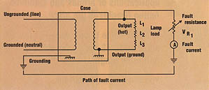
I have received several questions about whether reversing the input leads makes any difference. With "old style" transformers, switching polarity doesn’t matter, but UL 2161 also requires the SGFP device to work when the transformer’s ground lug is not connected. In this case, the neutral (-) terminal is used to sense a secondary ground fault (Figs. 1 and 2).
This doesn’t work if the line (+) wire is connected to the negative terminal. If the protection circuit cannot determine whether the positive terminal is connected correctly to the line conductor, it shuts off the transformer for safety. To determine which conductor is live and which is neutral, the circuit needs a reference to ground. Thus, a UL 2161 transformer must have its ground lug firmly connected to ground.
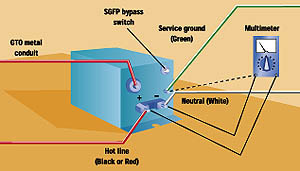
For this reason, many manufacturers require installers to run a separate ground wire directly from the power source (fusebox or panelbox) to the transformer. Ground and neutral wires connect to the same terminal bar at the power source. Running a separate ground is always wise because you never can rely on EMT conduit to carry ground effectively. This is because of the many couplings joining EMT sections, each of which creates a small threshold resistance.
If polarity is reversed in the wires feeding the receptacle for a plug-in neon sign, a portable sign might fail when connected, but then work perfectly when plugged into a properly wired outlet. Therefore, when you receive a service call for a recently installed, UL 2161-compliant plug-in sign, you can frequently save a needless trip by asking your client to try using another outlet to operate the sign.
How good is your ground?
For electrical installers, only one ground potential exists — all grounded equipment is at the same potential. But radio-frequency and sound engineers know that there can be different kinds of ground in electrical systems, and this can make a big difference in determining how to connect a device.
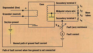
Until the UL 2161 requirements took effect, "ground" for all neon installations meant an equivalent potential of zero. But this is no longer true. Imagine a small core-and-coil transformer with one end of the secondary grounded (Fig.3).
If this end were directly connected to ground, the neon tubes’ normal operating current would pass through the ground, and the protection circuit could not distinguish between normal operating current and fault current.
Therefore, the secondary "ground potential" output terminal is connected internally to the fault sensor, and it must not be earth-grounded. If this terminal is grounded, the protection device may trip constantly when power is applied, or not at all, depending on the type of protection device. Because the primary ground connector is not the same as the secondary ground-potential connector, installers should not confuse these connections.
The same situation applies to midpoint-return transformers. The installer must run an isolated return wire (preferably GTO) to the transformer’s return terminal — not to the ground lug. The return terminal also cannot be connected to the primary ground lug. This can cause nuisance tripping or malfunctioning of the protection circuit.
Capacitance counts
Because the UL regulation requires protection devices to trip at fault currents of 15mA rms — and it’s common practice to install transformers with high secondary voltages (10,000 volts or more) — a problem arises. For legal installations, GTO wire typically must be run through grounded metal conduits. As discussed previously, the GTO and conduit form a capacitor. Because alternating current is conducted to a certain extent by capacitors (depending on frequency and capacitance), GTO in conduit generates current from a secondary terminal to ground.
In humid, outdoor environments where insulation is less than ideal, additional leakage current adds to the capacitive current, quickly reaching the 15-mA threshold. Therefore, unequal or excessively long lengths of GTO in conduit frequently cause nuisance tripping of UL2161 transformers. As a result, architects, sign designers and installers must always remember to place neon transformers as close to the tubing as possible and balance the lengths of both secondary legs as closely as possible.
Animated UL 2161 signs
Another frequently asked question is how secondary fault protection affects animated installations. The answer is, "Not very well." The UL standard dictates that removing and reapplying input power to a tripped SGFP transformer resets the protection device to normal. If the fault persists, the protection will trip again within 0.5 seconds after power is reapplied.
This creates problems in animated circuits, particularly where flashers switch the transformer on and off very rapidly. Each time the flasher energizes the transformer, it produces an arc mimicking a fault. Because such arcs can continue for only 1/2 second before the SGFP device trips, the protection circuit may be rendered useless in signs with rapid animation.
Based on my contacts with various transformer manufacturers, only a few of the currently available UL 2161 models are designed to operate with flashers.
Because UL 2161 does not permit the SGFP circuit to be accessible, you cannot field-wire the device to supply it with uninterrupted power. Considering that the SGFP device’s output to the transformer is switched by the flasher (as European regulations require), manufacturers must provide protection circuits fast and durable enough to withstand flasher operation. Therefore, if you’re installing an animated sign according to UL 2161 requirements, the transformers must be specified for this type of service.
I’ve seen some cases where protection devices caught fire because they could not withstand frequent on/off cycling. Thus, despite the benefits of secondary fault protection, designers and installers still need to play it safe.

SPONSORED VIDEO
Introducing the Sign Industry Podcast
The Sign Industry Podcast is a platform for every sign person out there — from the old-timers who bent neon and hand-lettered boats to those venturing into new technologies — we want to get their stories out for everyone to hear. Come join us and listen to stories, learn tricks or techniques, and get insights of what’s to come. We are the world’s second oldest profession. The folks who started the world’s oldest profession needed a sign.
You may like


Advertisement
Subscribe

Magazine
Get the most important news
and business ideas from Signsofthetimes Magazine.
Advertisement
Most Popular
-

 Tip Sheet1 week ago
Always Brand Yourself and Wear Fewer Hats — Two of April’s Sign Tips
-
 Photo Gallery2 days ago
30 Snapshots of the 2024 ISA Sign Expo
-

 Ask Signs of the Times4 days ago
Why Are Signs from Canva so Overloaded and Similar?
-

 Real Deal1 week ago
A Woman Sign Company Owner Confronts a Sexist Wholesaler
-

 Benchmarks6 days ago
6 Sports Venue Signs Deserving a Standing Ovation
-

 Women in Signs1 week ago
2024 Women in Signs: Megan Bradley
-
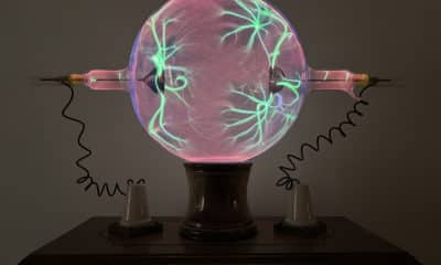
 Photo Gallery1 week ago
21 Larry Albright Plasma Globes, Crackle Tubes and More
-

 Women in Signs1 week ago
2024 Women in Signs: Ashley Borell