When several neon tubes are connected together to a neon transformer in a series circuit and power is applied, which tube lights up first? Whether or not all tubes will light up at once has been discussed at large, leading me to this month’s scientific approach to prove which idea is correct.
The (not so) simple theory
Consider a transformer supplying a circuit of four neon tubes. When the transformer is switched on first (or after each half cycle of the alternating current has passed through zero), all tubes haven’t yet started and therefore, don’t conduct electricity. Each tube starts to conduct when the voltage across it has risen to the ignition or starting voltage, and the gas becomes ionized. Thus, when the transformer voltage reaches the sum of all four tubes’ ignition voltages, all tubes start to conduct at the same time.
Kirchhoff’s first law of electrical current, which supports this theory, states: The electrical current in a closed circuit with no knots or forks is the same value at every point at every time (I=constant). According to this law, each tube receives the same current at the same time, so all tubes start simultaneously.
In contrast, our experience is somehow different. Neon professionals have likely seen a broken neon circuit that was energized. The tubes in this circuit will light up from the side connected to the transformer terminal and dim near the broken point. Thus, the neon tubes will light even if there’s no closed electrical circuit, contradicting our theory.
Why should tube #1 start at all? Because all tubes don’t conduct electricity, the piece of GTO wire between tubes #1 and #2 is completely insulated (by the nonconductive tubes #1 and #2) and doesn’t carry any defined voltage. As a result, there’s no voltage across tubes #1 and #2 to start.
If this was accurate, a series circuit of neon tubes wouldn’t start at all, which is untrue, as everybody knows. Thus, what causes tube #1 to start? A footnote to Kirchhoff’s law provides a clue: In alternating current circuits, the sum has to include all capacitive currents.
Now, when I included GTO capacitances to ground, and the voltage is applied first, C1 (the capacitance of the GTO running from the transformer to the left electrode of tube #1) is charged. As C2 (the capacitance of the GTO between tubes #1 and #2) is still uncharged (the same voltage on both sides), the GTO between tubes #1 and #2 has ground potential, placing ground potential at the right electrode of tube #1.
Momentarily appearing across tube #1, the full transformer voltage ignites the tube, causing it to conduct electricity. The flow of electricity through tube #1 will immediately charge C2 to the transformer voltage, minus the operating voltage consumed by tube #1. At that time, further capacitances are uncharged, and the same start scenario repeats with tube #2 and so forth.
Consequently, with capacitance present, the tubes fire in series from the transformer terminal toward the grounded end of the circuit, which, in case of a mid-point grounded installation, is the center of the tube series.
Defining tube startup
Before we continue with the experimental poof, we must know exactly when a neon tube starts. A physics-book definition states: A self-sustaining gas discharge is established when the ion multiplication factor exceeds unity. But this factor isn’t accessible for measurement directly or easily, so we have to use other parameters as indication.
When I measure tube current, the starting point is obstructed by capacitive charge currents of C1…Cn. When I measure the tube voltage breakdown (from the tube’s ignition voltage to the lower operating voltage), the delay of flushing the energy stored in the capacitances C1…Cn won’t provide the exact starting point of the tube. So what’s left?
Physically, when the tube starts, the number of ions increases like an avalanche in fractions of microseconds. Every ion will almost immediately return back to normal state under trapping an electron and emission of the desired (neon) light.
Thus, we can say a neon tube starts when it starts to emit light. If we take a very fast electric eye (or photocell), we can accurately determine the moment a neon tube starts.
Experimental science
Being an experimental physicist at heart, all theories are foggy unless proven by experiment. Thus, I prepared three, equal, 12mm-diameter, 5-ft.-long, clear glass tubes and filled them with pure neon at 15mbar (theoretically, they should require a transformer voltage of 5,364V). I connected them in series to a single, end-grounded (for my instrument’s sake), core-and-coil transformer of 6kV, 15mA. A 1 Ohm resistor was placed in the grounded side GTO to measure current after the last tube, and a Tektronix P6042 50MHz current probe was used on the high-voltage end of the secondary transformer.
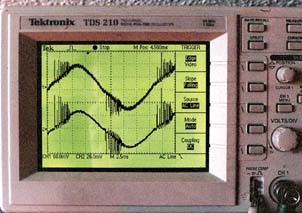
The experiment didn’t show any difference in the current starting point on both probes, even if I increased the oscilloscope resolution to approximately 5 nanoseconds per division. Fig. 1 shows that the current in the ungrounded side GTO and grounded side is exactly the same. What we see at a higher timing resolution are only the first oscillatory peaks in the little ringing as the transformer is loaded to approximately maximum tube length.
Any GTO run introduces capacitance. The experimental introduction of approximately 60 ft. of GTO — which may not be standard, but legal according to NEC 600-32(j) — between tubes #1 and #2 provides a completely different result. The large capacitance C2 introduced will delay the start of tubes #2 and #3 for more than 1.5 milliseconds. This isn’t peanuts, as a half-cycle at 60Hz line frequency lasts only 8.3 milliseconds, and therefore, tube startup is delayed by approximately 18%. But as previously mentioned, the best way to determine a tube’s true starting moment is to document when the first light flashes.
To detect the tube’s first flash of light, I referenced an old photomultiplier whose datasheet stated a maximum response time of less than 7 nanoseconds, which I consider to be fast enough. Because photomultipliers are sensitive to nearby electric and magnetic fields from high-voltage or magnetic transformers, setting up the sensor required excluding all electric and magnetic fields. Faraday cage shields didn’t help clarify the signal, therefore, I used distance to the tube and a telescope to focus only on the desired part of the neon tube, which produced a clean signal.
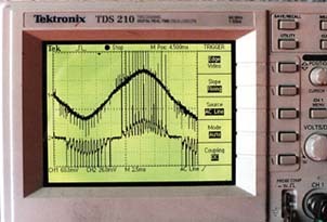
Without the large GTO capacitance, the photosensor didn’t show any difference in time of current rise or first flash of light, even at high resolution and regardless of whether it was focused on the high-voltage end or grounded end of the tube series (Fig. 3). Contrary to my expectations, the light contained ample noise and plasma oscillations — effects that are too complicated to discuss here.
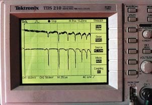
Anyway, things get really interesting when you touch the tubes. Fig. 4 shows that touching (introducing a little capacitance to ground) the ground-end tube will produce light output before current starts to flow in the GTO between the transformer and first tube. This can only be explained by remaining charges on the glass wall and other secondary effects. But the curve shows that the intensity of these early peaks is very weak.
We can also determine that the light output goes back to about zero between the ringing spikes. Thus, the tube really flashes, in contrast to the current curve, which exhibits a current flowing (the charge current of the total capacitance). As a result, there are multiple effects that influence the tube’s starting behavior.
Ultimate conclusion
Contrary to initial thoughts, a little theory proves that, in a series of neon tubes connected to one transformer, the tube on the high-voltage side should start first. Finally, the experiment reveals that the effects of GTO capacitance are more important, and all tubes merely start the same time when installed properly. Thus, this very interesting question of which tube starts first in a circuit has only one consequence for the practical neon installer: Avoid capacitance wherever you can; dimension and layout your circuit well, and all your tubes will start at once.


 Tip Sheet3 days ago
 Business Management1 week ago
 Women in Signs2 weeks ago
 Real Deal4 days ago
 Editor's Note1 week ago
 Line Time2 weeks ago
 Product Buying + Technology1 week ago
 Women in Signs4 days ago