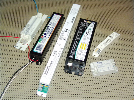
For several years, electronic fluorescent ballasts have been used successfully in many lighting applications, but standard, magnetic ballasts still maintained majority use. But people’s minds and regulations change, and energy savings and environmental protection are again priorities.
Since 2000, an official EU regulation mandates energy-saving ballasts for fluorescent lighting, either by improved magnetic ballasts or electronic ballasts. Electronic ballasts can operate a fluorescent lamp more efficiently than magnetic ballasts because they can convert, via a high frequency switching circuit, line voltage into higher voltage of limited current. These circuits’ characteristics towards the line and the load differ from those of magnetic ballasts (which an installer must consider to prevent future problems).
Magnetic ballasts are very reliable, even in environments that are rough on electronic equipment (high humidity or temperature, or a long distance between the lamp and ballast).
Surge line currents
Electronic ballasts are, almost exclusively, semiconductor circuits that need direct current (DC) for operation, so the alternating line current (AC) must be converted (or rectified) first. A capacitor provides a power reservoir to smooth out the available DC power when the AC voltage is lower than maximum in every 60Hz half cycle.
Advertisement
This capacitor, or reservoir, is completely empty when the ballast is switched on, and this reservoir is filled almost immediately, which creates a huge current demand on the line for a short time. Magnetic ballasts, in contrast, have a delayed and random start time; thus, many paralleled units won’t produce such a high surge current. When multiple ballasts are fed from one branch circuit (this happens in large, lightbox, pole signs, where up to a few hundred fluorescent lamps operate in a small area fed by a long supply line), this high current can trip a fast breaker or RCD switch. Because the capacitor’s charging current flows only when the AC voltage is higher than the capacitor voltage, standard electronic ballasts’ current demand is non-sinusoidal.
This non-sinusoidal current demand creates a bad power factor and harmonics in the line. Therefore, in Europe, electronic ballasts that exceed 25W of power must employ a special “active power factor correction” circuit to restore the current waveform in continuous operation. The remaining startup surge can present a problem in large installa- tions run off a three-phase supply line in WYE mode. Three-phase transformers are connected in a delta (shaped like a triangle) or WYE (shaped like a Y) connection.
In a WYE connection with sinusoidal current, currents in the three phases negate each other at the neutral conductor’s connection point (often called the “star point”); thus, the total current in the neutral line to the panel is normally zero in a perfectly balanced, WYE-connected system.
Not so with electronic power supplies! Because the current flow is either zero (when the AC momentary voltage is lower than the capacitor voltage) or high (when it’s charging, AC voltage is higher than DC at the capacitor), the currents don’t necessarily cancel out each other in the WYE connection’s star point, which causes high, non-sinusoidal current to flow through the neutral conductor to the panel.
When the neutral conductor size isn’t designed for this high current (it should carry no current in a perfect WYE connection) and is considerably lengthy (as in most sign installations), the neutral conductor’s resistance can cause the voltage at the star point to rise considerably. When this voltage is added to the other phase voltages, this momentarily unbalances the WYE scheme, the electronics in the other phases can receive a much higher supply voltage, which can cause damage. I inspected a pole sign where the surge current through the neutral conductor was roughly 400A (the sign’s normal operating current was approximately 16A per phase) during power-up.
High frequency
Advertisement
Electronic ballasts operate on the principle of high-frequency switching. Thus, a tiny inductor can sufficiently limit the current to the lamp. High-frequency current fed through fluorescent lamps produces a higher light output than the same current at line frequency.
High-frequency currents can be easily radiated outwards from conductors (radio transmitters are high-frequency power supplies that can add information to the output current). Most manufacturers limit the lead lengths from the ballast to the lamp to corral the radiated energy and keep the additional capacitive load to the ballast low.
To do this, leads that emerge directly from the ballast must not be extended, or, when terminals are provided, the leads attached by the installer must meet these requirements. Often, one pair of terminals can be used with longer leads (on the grounded side), so the lead pairs must not be changed over.
Another no-no: bundling the leads from several ballasts to a group of lamps. In this case, one ballast can influence the other, which causes the high-frequency oscillators to lock and, thus, overload them. Keep leads well separated from each other and from grounded metal. This is often disregarded — lead length or bundling has absolutely no effect on group installations when magnetic ballasts are used.
Instant start vs. preheat
Fluorescent lamps employ hot-cathode electrodes to reduce starting and operating voltage. Thus, the electrodes must be brought to operating temperature (roughly 1,300° to 1,500° F) first. For this reason, the magnetic ballasts brought out two leads to each lamp end to heat the electrode filament.
Advertisement
Electronic ballasts can provide enough output voltage to instantly start a lamp without preheating it with cold electrodes (like a neon tube), so there’s almost no delay between switching on the lamp/ballast and producing light. Nevertheless, “instant start” ballasts, which have only one lead going to each lamp end from the ballast, will knock off a small electrode- activation mass with each lamp start. Thus, “instant start” ballasts should be used only in minimal, on/off switching applications, because frequent on-off switching reduces a fluorescent lamp’s life remarkably .
In contrast, modern “preheat” electronic ballasts can achieve a lamp lifetime of 15,000 to 25,000 operating hours regardless of the number of switching cycles. The microprocessor control first measures the electrode’s type and temperature, applies only a preheating power and measures the temperature (by filament resistance) while heating up. When both electrodes achieve operating temperature, a short ignition pulse ignites the lamp. Then, the lamp operates on constant current. Because it can sense the voltage, the ballast also can detect potential lamp failure, or, if it’s running hot, it switches the lamp off before it creates a bad appearance.


 Tip Sheet1 week ago
 Photo Gallery3 days ago
 Ask Signs of the Times4 days ago
 Real Deal2 weeks ago
 Benchmarks1 week ago
 Women in Signs2 weeks ago
 Photo Gallery1 week ago
 Women in Signs1 week ago