For most of the industry’s history, U.S. neon shops selected transformers very simply: the still prevalent "one size fits all" mentality. But, the standard 15,000V/30mA transformer doesn’t perform well under all circumstances. Using the correct neon transformer maintains low operating cost and maximizes a neon sign’s life.
Theoretical approaches
Transformers are commonly selected using a footage chart. Most transformer manufacturers offer such loading charts, which provide a rough guideline that only matches their transformers. Neon transformers vary by manufacturer and model.
Is there a universal loading formula? Neon tubes’ physics haven’t appreciably changed for decades. Surprisingly, all formulae I’ve found have been determined empirically. Among different approaches, I’ve found the gradient method best matches measured values (see Handbuch der Lichtwerbung (in German), G. Gut, 1974, Deutsche Verlags-Anstalt, page 73).
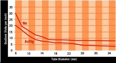
The method’s premise espouses that the voltage required for a certain tubing length depends upon the type of gas and tube diameter. The smaller the tube, the more ions are lost on the glass wall, and, thus, a higher voltage is required to sustain the gas discharge. For each tube in a sign, use the tube diameter to obtain the gradient (Fig. 1), then multiply it by the correct tube length. Note that the glass sticks don’t provide a correct length; glass stretches in the bends, so you’ll need a blowhose to determine the exact glass length. Then, add the electrode-loss voltage, which is 200V per system for argon/mercury and 150V for neon. The result is your theoretical operating voltage.
The tubes need more voltage to ignite. To determine the required transformer voltage, multiply the operating voltage by 1.5 for argon/mercury and 1.8 for neon. Repeat this procedure for each tube in the sign, and tally the total for all tubes you want to put on one secondary circuit.
Then, choose the transformer with the next-higher voltage level, and verify that this accommodates a 5 to 10% safety margin that accounts for tube aging and cold winter nights.
Networld
The virtual world offers many hints and tools for neon-transformer calculations. The Neon Calculator can be downloaded from Krypton Neon’s (Long Island City, NY) homepage, www.neonshop.com/software. Users receive a 30-day free trial, and a full license costs only $25.
To obtain your required voltage, enter the sign’s tubing parameters, and the site will automatically compile the required secondary circuits. The system also automatically divides tube lengths, such as those needed for large border jobs.
Submit a total luminous length, tube diameter, fill and the desired maximum transformer voltage, and the program suggests an optimized tube length, the number of circuits and total load. Need more?
Theory vs. practice
But all theory is foggy. The best way to match a neon transformer with an actual sign is to measure the required ignition and operating voltages of the sign’s tubes. Several transformer manufacturers offer tools to test the operational transformer/tube combination. Most contain a variable, line-voltage transfomer (variac), line-voltage meter and a milliamp meter to measure the transformer’s secondary current. The common "flicker test" measures secondary current and varying line voltages.
I’ll roughly outline one of several ways to execute this test. First, remember two important points. Use only true AC milliamp meters in a well-insulated enclosure rated for at least 15,000V. Also, never touch the instrument while the connected circuit is energized. I have fried several inadequate meters and been zapped more than once.
For the first step, connect the tested transformer to the metered variac output; connect the AC milliamp meter directly across the transformer’s high-voltage terminals.
Next, adjust the variac to read the nominal, secondary, short-circuit current. U.S. transformers are rated in short-circuit currents, whereas European transformers are rated based upon operating current. For example, a U.S. 9,000V/30mA transformer reads 30mA in short circuit when the adjusted voltage matches the nominal voltage stated on the transformer plate. Switch it off, but don’t change the variac setting.
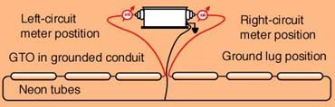
Third, connect the neon tube load in series with the milliamp meter according to Fig. 2. Switch it on and read the current. The current under load for a typical U.S. transformer will read 75 to 85% of the short-circuit current, which represents 22 to 25mA for a 30mA model. From a voltage standpoint, a lower current overloads the transformer, which means that it’s powering an excessive tubing length. Higher current may cause the transformer to run hot. Note that, for mid-point, return-wired circuits, you must separately measure each leg of the secondary grounding because a midpoint-grounded installation behaves like two separate transformers within one case.
Finally, reduce the primary voltage using the variac. For a 120V, U.S.-style transformer, you can reduce the voltage to 85 or 90V before the tubes start to flicker. If they start flickering at 90 to 100V, your transformer’s voltage is insufficient, and you should opt for the next larger size.
European transformers behave differently, because their short-circuit current to operating current ratio is higher. In this case, the operating current under load must be within the range given by the transfomer manufacturer; the average value must be stated on the transformer plate. Loading European transformers is more critical, because they don’t permit the wide range of loads that U.S. models allow.
A helpful tool
For a few years, the Selektor has performed load-performance tests and determined the proper transformer to use. Manufactured by Standard Neo-Lite Inc., and sold by Allanson (Toronto), the device contains a transformer and digital circuits that evaluate the ignition and operating-voltage characteristics of your tube’s actual load.
By connecting it to the installation’s tubing and flipping a switch, this device indicates the correct transformer size. The device will pay for itself over time, because a properly matched transformer will provide maximum neon-tube life-span and generate satisfied clients.
A word about safety
I’m a professional sign inspector. Most premature sign failures are caused by improper transformer loading, improper secondary wiring (remember, keep it as short as possible) or improper line-voltage conditions. Always make sure that the transformer terminal’s supply voltage under load is within the specs. Provide good ventilation of the transformer in the box.
It’s preferable to divide a total tube load into multiple, smaller circuits of lower voltage. Electrical problems arise far more frequently when voltage exceeds 10,000V. Therefore, 15 9,000V transformers will be less problematic than nine 15,000V units.
Left-circuit meter positionRight-circuit meter positionGround lug connectionGTO in grounded conduitNeon tubes
Sample Calculation
This sample calculates the transformer load for a single-stroke, block-letter sign reading "Motel"; the "O" is red, and the other letters are green and comprise 2-ft.-tall letters and 15mm tubes.
The "M" is 84 in. in actual length. For argon/mercury, we obtain a gradient of 8.2V/in. from Fig. 1. Thus, the gradient (8.2) multiplied by the length (84 in.) totals 689V. Add 200V for a pair of electrodes, which tallies an operating voltage of 889V. To obtain the ignition voltage, multiply the operation voltage by 1.5, which results in an ignition voltage of 1,333V.
The "O" has 37 in. of neon. For 15mm neon tubes, we obtained a gradient of 10.5V per inch from Fig. 1. A length of 37 in., multiplied by the gradient, yields 388V. Adding 150V for one pair of electrodes in red neon accounts for a 538V operating voltage. For neon-filled units, multiplying the 538V by 1.8 results in an ignition-voltage figure of 968V.
The other characters in three tubes require 2,597V of ignition voltage. As such, our total ignition-voltage sum is 4,898V. Further, we need to factor in 10% for tube aging and cold weather; thus, our voltage range is 5,388V. So, we choose a 6kV transformer.


 Tip Sheet1 week ago
 Photo Gallery2 days ago
 Ask Signs of the Times4 days ago
 Real Deal2 weeks ago
 Benchmarks7 days ago
 Women in Signs2 weeks ago
 Photo Gallery1 week ago
 Women in Signs1 week ago