Carbon-arc lamps enjoyed widespread use in the early days of electrical lighting, but they were simply too bright for indoor use. Also, each lamp had its own circuit and power source, which meant that "dividing" these lamps into smaller units would’ve been problematic to residential applications.
Many large, neon installations also pose a "division" problem. How do you divide a large number of tubes into appropriate circuits and match them with the correct transformer? Many sign companies don’t know. I’ve inspected numerous installations that were built without adequately planning the circuit division.
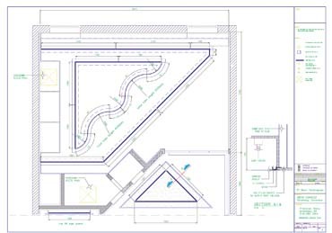
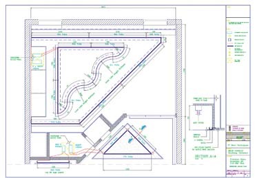
This month, I’ll explain how to properly lay out neon/cold-cathode circuits. Cold cathode’s long, linear tubing runs may present more difficulties than a neon installation, but both follow the same layout rules. I’ll use a cove-lighting installation (Figs. 1 and 2) as a base for my layout method.
Author’s note: I didn’t convert metric measurements in the drawing, because the calculations are much more complicated in feet and inches.
Step by step
First, divide the lit lengths provided by the architect into useful tube-length sections. I don’t specify 8-ft. lengths, because some glass (which normally comes in 6- or 8-ft. sticks) arrives with cracked ends. When you cut tubes, allow at least one extra inch. Also, make many tubes of the same length to simplify manufacturing and exchangeability of glass sections.
Splitting glass lengths requires experience. Initially, you probably won’t get the right dimension. I start with the long straights and end with the fit tubes at the corners. Then, I often re-specify the straight lengths to obtain the most universal standard length (Fig. 1).
Next, the transformer requirements are calculated. The old, "one size fits all" method leads to many installation problems and premature failures. This method totals all tube lengths and adds 1 ft. more per electrode pair. For example, using the old method, Fig. 1 would require 108 ft. 4 in.
We’ll say we’re using 25mm cold cathode filled with argon/mercury. Referring to an ANSI-standard, transformer-loading chart, I see that one, 15kV, 120mA transformer would run 120 ft. of 25mm argon/mercury tubing indoors. Thus, 108 ft. 4 in. would fit.
If, instead, I would target 7,500V transformers to decrease the used voltage, each would run a maximum of 70 ft. For 108 ft., I would need two to run the length, with some reserve. But, if we stay with one 15/120, or two, 7.5/120s, we must wire all tubes in one or two circuits, and we’d plan to run extensive GTO across the room. In addition, the higher the voltage, the louder the "buzz," which must be avoided in conference rooms, as in this installation.
Two, 7,500V transformers wouldn’t make any difference


 Tip Sheet1 week ago
 Photo Gallery3 days ago
 Ask Signs of the Times5 days ago
 Real Deal2 weeks ago
 Benchmarks1 week ago
 Paula Fargo12 hours ago
 Photo Gallery13 hours ago
 Women in Signs2 weeks ago