For more than a decade, electronic neon transformers have operated indoor signs. However, they’ve overcome most of their "childhood" problems — compatibility issues between microelectronics and high voltage often led to reliability issues — and are increasingly used for outdoor applications.
But, simply changing an existing installation from a magnetic to an electronic transformer may end in disaster. Thus, this month’s column answers frequently asked questions and tells how to avoid mistakes when installing electronic neon-power sources.
Fire and water
Electronic neon power supplies operate at high frequency and high voltage. Physical laws governing direct current (DC) are easy to explain; alternating current (AC) — think three-phase, power factor and such — require lengthy discussion. High-frequency circuits are almost impossible to explain in simple terms. As such, most electricians perceive that high-frequency circuits carry a black-magic aura.
However, they’re not too difficult to understand. Most electricians are indoctrinated with the basic rule, "Grounding makes the circuit safe." For this reason, electrical wires are installed inside grounded, metal enclosures and conduit. Conversely, high-frequency, high-voltage electricity must be kept far from any ground or metal.
Why is a practice that’s fundamental to one electrical system hazardous to another? We’re not addressing different kinds of electricity; their physical laws are the same. However, AC’s general properties are dictated by its frequency, measured in hertz (Hz). The higher the frequency, the more easily energy radiates into space around the conductor. Radio transmission frequencies typically measure several million Hz. The higher the frequency, the more easily energy radiates into the surrounding space.
Advertisement
Obviously, in signage applications, we want to harness this energy into light in our neon tubes, and not allow it to radiate from the power supply into space. Thus, the guidelines for neon systems powered by electronic transformers aim to curtail radiation from the power supply into space. Safe installations are rooted in knowledge of high-frequency, high-voltage properties. $image1
Capacitance
I’ve discussed the neon-sign capacitance issue before (see ST, April 2001, page 36; October 2001, page 28; and January 2003, page 18), and I’ll summarize it again.
Every conductor can become electrically charged. Thus, electrons repel each other, and they accumulate on the conductor’s outer periphery. A stronger charge attracts more electrons, which packs them more tightly together. The tightly packed electrons subsequently "push" against each other. This "pushing" of electrons charges a conductor.
The larger the conductor, the more electrons that are needed to reach a certain pressure (or voltage). Switching on a DC circuit supplies these electrons only once. AC-voltage polarity reverses 120 times per second. Therefore, the charge is removed and reapplied in reversed polarity every half cycle. (Physicist’s note: As with electricity, we’re dealing only with negatively charged electrons; positrons, which apply only in nuclear physics, are unstable in our environment.)
We must supply, or remove, the same amount of electrons at the conductor’s periphery to obtain a uniformly strong, reversed polarity. This results in a charged current that flows back and forth between the power source into the conductor — our GTO cable. The current linearly increases as the GTO’s length, or the voltage, is increased. Therefore, when you use a 15kV transformer, the charged power is four times stronger than in a circuit powered by a 7.5kV transformer. But when the spacing from an adjacent conductor of opposite polarity increases, the current decreases in linear fashion.
Advertisement
Each time polarity reverses, energy is expended to remove and rebuild the charge. The more frequently the polarity changes, the more electrical power is needed to build up, and remove, the voltage or charge. For this reason, an electronic power supply operating at 40,000Hz generates a capacitive current 666 times stronger than a magnetic transformer operating on 60Hz. Keep in mind that every neon tube becomes its own conductor when energized. Based on these characteristics, therefore, we can derive important installation rules for electronic neon transformers. $image2
Magnetic fields
Every electrical current causes a magnetic field, which surrounds its conductor. The faster the current changes polarity, the stronger the magnetic coupling to adjacent conductors. An electronic power supply’s small, internal, magnetic transformer generates high voltage, but it operates on a high frequency. This causes the magnetic field to radiate well beyond the transformer into its surrounding space and induces electric currents in every metallic surface next to the transformer.
For this reason, most electronic transformers can’t be mounted directly on metallic surfaces, but on 1/2-in.-thick, or wider, nonmetallic spacers. If a transformer is mounted on metal, the induced currents may draw power from the transformer and heat the adjacent metal. Some circuits react to the increased output current by overheating. To illustrate a worst-case scenario, I once observed an electronic transformer destroyed by circuit overloading when a strong magnet was placed nearby during operation.
Outdoor signs
High-frequency electricity ionizes gas more easily than conventional line-voltage power. Ionization occurs not only in the fill gas of a neon tube, but also in the surrounding air. Thus, two, closely spaced tubes of opposite potential (for example, the ends of a large circle or the letter "O") should always be separated by at least 1 in. to prevent arcing.
Advertisement
Do not use tie wire and cork to support neon tubes when using electronic power supplies. High-frequency electricity will shortcut through the tie wire and puncture the glass. Also, avoid wire strands that protrude into space at secondary connections; a destructive corona may develop around sharp points at high frequency (as in a spark coil).
Also, nearby fluorescent lamps and neon tubes that are switched off can suddenly illuminate via the electromagnetic energy that radiates from energized parts of the high-frequency circuit.
Water trapped between insulated wires and metal surfaces increases the capacity by a factor of 81. Therefore, electronic power supplies should be limited to a maximum output of 2,000V. This even applies to well-sealed signs, in which internal condensation is the only moisture source.
To reduce the destructive effects of capacitance, electronic power supplies must be mounted closely to the tubing they operate. Thus, they may be exposed to high, outdoor temperatures. Unfortunately, few power supplies incorporate self-resetting thermal protection. Check that all manufacturer requirements are met, so warranty replacement isn’t voided in the event of failures.
Finally, don’t forget that every high-frequency, electronic power supply — whether for operating neon tubes, fluorescent lamps or a computer — creates radio interference. Even if a single unit may be designed within legal limits, the high number of power supplies in operation worldwide makes long-distance radio reception impossible in many cities. This is more than a technical problem — it impedes the free transmission and receipt of information, one of our basic human rights.
Electronic Power Source Don’ts
* Don’t extend the GTO attached to the supply unit by the manufacturer. If possible, cut the leads shorter — every surplus inch harms the supply.
* Don’t install the GTO in metallic conduit.
* Don’t use braided or shielded GTO cable.
* Don’t install the neon tubing on metallic surfaces.
* Don’t cross GTO leads or run nonmetallic conduit parallel to one another.
* Don’t run neon units of opposite polarity close together.
* Don’t use metallic tube supports.
* Don’t interconnect multiple sign letters and run them on a single electronic transformer. One letter, one power supply.
* Don’t permit any loose, secondary connections, such as housings with improperly adjusted springs. Sparking and arcing caused by poor connections creates very short pulses and oscillations, which damage electronic power supplies in fractions of a second.
* Don’t operate an electronic power supply with an open secondary circuit (no load connected).
Electronic Power Source Do’s
* Keep the GTO cable short. Don’t exceed 4 ft. from the power supply to the last tube.
* Use secure primary wiring, heavy-duty switches and slow-blow fuses. When switched on, electronic power supplies draw a surge current measuring 20 to 100 times the normal operating current.
* Ground every metal portion of the sign carefully, but use extremely short jumpers. Even an insulated screw head can draw sparks, because the screw can be charged by the surrounding electrical field.

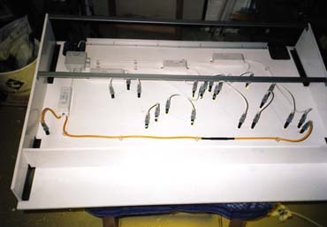


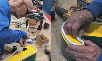


 Photo Gallery2 weeks ago
 Ask Signs of the Times2 weeks ago
 Paula Fargo1 week ago
 Real Deal6 days ago
 Photo Gallery1 week ago
 Women in Signs2 weeks ago
 Projects6 days ago
 Women in Signs2 weeks ago