In the past five years, energy-saving electronic ballasts have proliferated. Today, it‘s hard to obtain a magnetic ballast, even for replacements.
The ubiquitous electronic units’ properties and installation requirements differ from the magnetic units. Therefore, the sign installer must carefully select the proper ballast type and model for each purpose to avoid failures.
Regardless of ballast type, a fluorescent lamp ballast must fulfill three, main tasks:
1. Prior to lamp start, it must preheat the electrodes by running enough current through the filament wires. Once the lamp operates, the heating current must be reduced or switched off to avoid overheating the electrodes.
2. The ballast must provide high voltage across the lamp to start the gas discharge between the electrodes once the electrodes have been heated.
3. It must provide a high-enough voltage across the lamp, once the lamp has started, to sustain the gas discharge and, simultaneously, limit the operating current to a proper value for each lamp size.
Advertisement
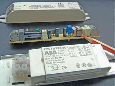
Electronic ballasts, which were first introduced in the late 1980s, use electronic components to convert 60Hz voltage and current to high frequency to operate a fluorescent lamp. Besides all electronics, one part remains the same: The magnetic choke still limits the current (see ST, October 2008, page 58), but the choke can be much smaller if the frequency is high enough (keep in mind that an inductor’s inductive resistance [impedance] depends on the frequency of the alternating current [AC]). Thus, at twice the frequency, you need only half the inductance to achieve the same, current-limiting action.
In modern electronic ballasts, the frequency is roughly 60 to 100kHz, or more than 1,000 times the main frequency. Thus, the inductance can be 1/1,000 or less to achieve the same purpose. Besides the advantage of less electrical loss, electronic ballasts also enjoy smaller sizes and less weight.
Modern semiconductors allow the ballast to convert direct current (DC), or generate DC by rectifying AC line voltage, into 60 to 100kHz high frequency with losses of only 1 to 2%, compared to magnetic ballasts’ 4 to 8% power loss.
High frequency also runs through the fluorescent lamp to preheat and operate it. And this causes most electronic-ballast problems. By conside¬ring how high frequency can be dissipated most easily into the surrounding space in the installation plans, many issues could be averted. High frequency is generated and used within the ballast itself and also in the relatively large space of the lamp installation. High frequency radiates much more easily into the surrounding space than line-frequency currents.
Wiring up
Advertisement
Electronic, fluorescent-lamp ballasts no longer require a starter switch. Thus, all electronic ballasts are either “rapid” or “instant” start ballasts. I explained the difference in the October 2008 issue, but, in a nutshell, the instant-start ballast uses only two wires per lamp. The electrodes aren’t preheated. Instead, a high-voltage strike starts the discharge, as in a normal neon tube, which causes the lamp to start immediately when power is applied.
The rapid-start ballast simultaneously applies starting voltage across the lamp while heating the electrodes at first.
Some ballasts that require a three-wire installation are instant-start ballasts, which don’t preheat the filaments, and run the tube in a two-wire configuration. The third wire determines if a lamp is inserted into the lamp holder – similarly to the “cut out” type of lampholder – and if the filament is still conductive. This prevents the lampholder from being energized if a lamp isn’t inserted, or the lamp has failed (in most cases of lamp failures, the filament burns out first).
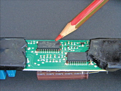
The most advanced electronic ballast is the so-called “intelligent” ballast. Controlled by a microprocessor, it determines the lamp type or wattage attached to the ballast. Thus, you need only one intelligent-ballast type (or very few) for various fluorescent lamps.
These ballasts, which must be installed with four wires per lamp, measure filament resistance at room temperature, apply a heating current and re-determine the resistance to measure the filament temperature. Each lamp type has its own particular, filament heat-up characteristic, and the ballast can select the proper operating voltage/current from these measurements.
Besides the obvious advantage, that installers don’t need to stock many types, intelligent electronic ballasts always bring lamp electrodes to the proper operating temperature before the lamp is ignited. Accordingly, the lamp life doesn’t entirely depend on how many cycles the lamp is being switched on; some manufacturers guarantee 25,000 operating hours or more for a matched-combination lamp/intelligent power supply.
Advertisement
There’s no gain without cost – I’ve seen “intelligent” ballasts fail even when the correct lamp type or wattage has been selected, because the lamp doesn’t contact the lampholder perfectly; thus, because the resistance wasn’t measured correctly, the lamp, in operation, didn’t receive the right amount of power. You can imagine the result when a ballast pushes 80W through a 28W lamp. This can be annoying, especially in outdoor applications, where the contacts are more or less exposed to humidity and temperature changes.
Electronics and outdoor signs
Most types of electronic, fluorescent-lamp ballasts, which comprise an open circuitboard placed in a metal or plastic box, are specified only for indoor, dry-location operation. But most illuminated, lightbox signs aren’t indoors and can’t be called “dry-location inside” – even with enough drainholes, condensation likely occurs.
Thus, some manufacturers (like Osram) offer special “outdoor kits,” in which the ballast must be installed in an additional, watertight enclosure. Without such an enclosure, electrolytic-corrosion effects (humidity) will damage the circuitboards very quickly – even varnishing or partial potting doesn’t protect it adequately.
Another outdoor-application issue is the maximum ambient temperature permitted during electronic power-supply operation. Electronics are much more sensitive than simple, core-and-coil magnetic ballasts. Especially when outdoor kits are used, air circulation, which cools the electronics, is restricted. Even in somewhat northern states, sign-cabinet internal temperatures can reach 180° F or more in summer when facing the sun. Such temperatures – even if not in operation – reduce the electronic ballast’s lifetime. (Mainly the electrolytic capacitors will dry out over time.)
A very important aspect for electric-sign installations, which normally involve multiple ballasts per sign (I‘ve inspected large pole signs with more than 300 electronic ballasts) is the inrush current that occurs when the sign is switched on. Most electronic ballasts com-prise the main side of a rectifier and a electrolytic capacitor, which smoothes the DC.
When the sign is off, the capacitor is completely discharged. When the main is switched on, the capacitor is charged in the first, half-wave of the main AC (or worse, if the switch is closed when the AC wave is at its maximum peak, the charging occurs in less than two or three milliseconds), which causes the current flow in the mains to be more than 10 to 20 times the normal operating value.
If one ballast is running a 60W lamp, the normal operating current is roughly 0.6A, so the surge, upon ignition, might reach 15A – no big deal. But, if the sign uses 10 such ballasts, we’re dealing, already, with a 150A surge current.
In large signs, I‘ve measured more than 800A surge currents per phase, which causes severe, momentary conditions for the entire, electrical-building installation.
In any three-phase installation, the difference in voltages in the phases at the switching moment causes a momentary asymmetry.
In WYE-connected signs, the asymmetrical current (which can be several hundred amperes, too) passes through the neutral conductor. If the neutral conductor isn’t very low resistance (a common situation), elevated, unsymmetrical, star-point potentials can occur and damage the electronic ballasts (see ST, February 2007, page 26). So, take utmost care to properly design the main connection and phase distribution when using multiple electronic ballasts.
Most models of Residual Current Detector (RCD) safety switches also can’t endure the momentary asymmetry or surge load (magnetic saturation in the current transducer) and will trip even if there’s no fault condition. Some electronic-ballast manufacturers specify using only electronic ballasts on RCDs with a delayed-tripping characteristic.
Arc fault interrupters haven’t been reported to cause nuisance tripping in connection with electronic fluorescent ballasts.
Electronic ballasts are also quite sensitive to main-line voltage surges and transients – something that doesn’t occur often in indoor/office applications. But, for signs in outdoor, commercial or industrial zones, line-voltage peaks might be caused by such large, inductive appliances as arc welders, large air-conditioning units, lift motors and transformers that are switched on/off momentarily. In such outdoor or rough, electrical, environmental applications, line-transient filters should be installed in the supply line between the panel and ballast(s).
Testing electronic ballasts onsite is limited to checking if connections are corroded and ensuring the lamps work. Check if there’s line voltage at the ballast’s terminals, and if it’s at the right level. Never attempt to take measurements with an electric meter at the electronic ballast lamp or output terminals – the high-frequency voltage across the wires (of equal color) that’s going to one electrode, or even across the lamp, will damage your meter and ballast, in most cases. This will damage your meter and the ballast, in most cases. Also, connecting a lamp with the wrong wattage can damage electronic ballasts.
Often, the lamp on an electronic ballast won‘t start, even if the ballast attempts it (when you switch the lamp on, it starts to faintly glow from one end – but that’s difficult to see in daylight). This indicates the lamp’s starting voltage is too high, or the ballast doesn’t supply enough voltage to start the lamp.
Frequently, high-frequency power is drawn off from the lamp circuit by wires that are too long between the ballast and the lamp, of if a grounded metal strip must be installed 1 in. or less in distance, along the glass, which is essential to properly start the lamp. Also, never bundle wires between a set of ballasts and their corresponding lamps.
Electronic ballasts have been performing better than magnetic ones in many applications. However, if you need a bulletproof, outdoor installation, I‘d recommend milspec-like heavy-duty magnetic ballasts.
Rules-of-Thumb for Electronic Fluorescent Ballasts
Because of high-frequency electrical currents, the same rules that govern electronic, neon power supplies should be observed for electronic fluorescent ballasts:
• Never connect the lamp terminals of electronic power supplies in series or parallel to increase power.
• If an electronic ballast is designed to run multiple lamps, always install the exact number of lamps, and never leave an output open or unused.
• Keep the wires between the ballast and the lamp as short as possible.
• Never bundle the wires between the ballast and lamp.
• Keep wires at least 1 in. away from metal.
• Ground all metallic objects in the vicinity, because they can pick up power.
• When you have quick connects, use only the wire type required for the connectors, or the connection won’t be safe.
• In contrast to neon installations, some fluorescent lamps (especially long, high-powered T5s) require a grounded metal strip to be installed along the lamp, a maximum 1 in. from the glass, for a proper lamp start.
• To properly function, electronic ballasts must be correctly grounded (if they bear a grounding terminal).
• Unless explicitly specified, electronic ballasts can’t be dimmed or flashed.
• Electronic power supplies are almost exclusively designed for indoor, dry-room applications. Special models and installation requirements apply for outdoor service.
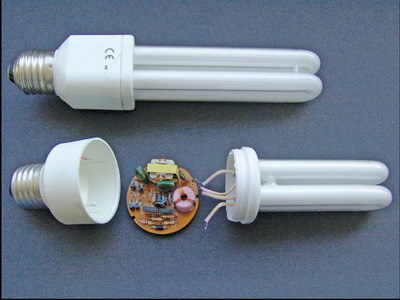
• Small, electronic ballasts can fit into channel letters with energy-saving, custom-made fluorescent lamps.
Click here to read Fluorescent Ballasts, Part One.


 Big Survey1 week ago
 Big Survey2 weeks ago
 Photo Gallery6 days ago
 News1 week ago
 Heidi Tillmanns19 hours ago
 Editor's Note3 days ago
 News5 days ago
 News2 days ago