For many years at the ISA Sign Expo, I’ve heard salespeople doom neon to the graveyard. Nonetheless, after nearly 100 years, neon signs are still shining and will definitely continue.
At major industry shows, companies sell the newest neon-equipment developments as “must haves.” Don’t trust any salespeople. Decide for yourself after having carefully weighed what you really need. Do your homework well, especially if you’re considering a new neon-pumping system.
Vacuum
A complete (read: as good as possible) vacuum must exist inside a neon tube, and that vacuum must be achieved before the tube cools down after bombardment. If this doesn’t happen, the impurities loosened by the “cooking” resettle on the tube’s walls and won’t be removed. I‘ve discussed the pumping characteristics of different pump principles awhile ago (see ST, November 2006, page 26).
A two-stage mechanical pump won’t produce standard-quality neon; you need a secondary, or “high vacuum,” pump. The mechanical, or “roughing,” pump should have at least a 12- to 16-cfm capacity. The secondary pump can be a diffusion/aspirator pump or a turbomolecular/molecular drag pump (quite an expensive investment, but it consumes less power and has a quick startup).
Advertisement
Because of different characteristics, an approximate 20- to 40-liter/second diffusion pump or molecular drag pump is sufficient for processing two, 8-ft, 25mm-diameter, cold-cathode tubes at a time, but a pure turbomolecular pump should have at least a 100-liter/second capacity.
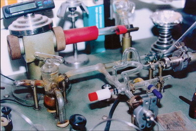
The manifold should be short and wide; the bore of the vacuum stopcocks, at least 12 to 15mm; the manifold tubing, not smaller than 20 to 25mm up to the tube connection. The only obstruction between the neon tube and pump should be the electrode tubulation; all other tubing should be large diameter.
For precise filling, a good needle valve is a must. Cheap valves/transfer systems tend to leak or stick before they can pay for themselves. The manifold must at least provide connectors for two (one flushing, one filling) or three (flushing, red and blue) laboratory, standard, 12-liter (1 liter at 12 bar), aluminum, gas canisters.
Should you construct the manifold from metal or glass? That’s a philosophy question. If you choose metal, you must ensure perfect electrical grounding. Glass is unsafe, considering flashbacks can hit you or your gauges. However, you can leak-test glass with the spark coil, and glass allows you to see if debris lingers inside.
Gauges
Measuring is knowing. Guesswork doesn’t work.
Advertisement
Use a sturdy Pirani or thermocouple vacuum gauge with platinum filaments. Avoid gold filaments, because gold combines with mercury vapor, then changes the readout – you might as well be guessing.
A well-grounded metallic mesh in the vacuum line prevents gauge-sensor destruction during an accidental flashback. Recalibrate Pirani gauges every six months, or take it (if you don’t own a McLeod gauge) to a service lab.
Filling gauges requires precision. I strongly advise against electronic gauges – especially piezo-sensor-based ones – except very expensive, capacitance diaphragm gauges (such as the MKS Baratron), because electronics lose calibration in a few months, and/or they can‘t take a neon shop’s high-voltage environment.
The (silicone) oil-filled U-gauge, once calibrated, will read accurately forever. However, the labor-inten¬sive gauge must be reset every pump cycle. Therefore, I recom¬mend a mechanical dial gauge, in the 0-40-mbar range, and use the U-gauge once a week to check the mechanical gauge’s calibration (the mechanical parts might get worn or bent when air rushes in too fast – for example, if a tube breaks).
To determine bombarder opera¬ting parameters, a sturdy, moving-magnet type, analog, AC-current meter, at 0-1000mA, is a must. I prefer the meters with large scales and dials (5 or 8 in.), because the meter must be installed in the bombarder’s high-voltage side – in an isolated box that’s beyond arm’s reach, but must be readable. Never use electronic digital meters here!
An analog, moving-magnet secondary voltmeter on the bombarder that reads 0-25kVAC, is good to have, but not a necessity. Regarding size, the same range as the milliamp meter applies.
Advertisement
Philosophies wildly diverge regarding temperature gauges. So, let’s look at facts. Bombarding should heat the glass tube as hot as possible without melting it. The chemical means of indicating temperature (such as thermal crayons, temperature-sensitive paints or [news]paper) merely indi¬cate that a given temperature range has been reached or surpassed.
Electronic thermometers, contrastingly, must withstand a high-voltage environment and are thus shortlived in a neon shop (we’ve all accidentally hit the temperature gauge with the spark coil while leak-testing a tube, which shoots through more than 80,000V). Sturdy, old-style (those that don’t need batteries) thermo¬couple gauge sensors are so massive that the metal sensor cools the tube where they’re attached. Thus, the sensors don‘t read the actual temperature (they read less) and can introduce stress cracks.
Readings of infrared thermometers vary on many parameters, such as glass type, coating and pointing angle, unless you own a very expensive spectrometer unit.
To be honest, thermocrayons and newspapers have worked well for me for more than 10 years, and I’ve tried all the other instruments.
The bombarder
Gentle but powerful – a bombarder must be both simultaneously.
Three parameters are important:
1. In the U.S., the open-circuit voltage should be 20,000V or higher for starting the tube.
2. The short-circuit current shouldn’t be less than 1,000mA, to properly convert electrodes up to 120mA – 12kVA isn’t enough for its kVA rating.
3. The secondary must be well isolated, and the control must be smooth and easily adjustable. For an electronic choke/control, the control knob should be large enough to be set in tiny frac¬tions of a turn – I‘ve seen tubes explode just by “giving it a little turn more” on a ½-in.-diameter knob.
Most electronic, silicon-controlled rectifier chokes distort the current waveform and produce high voltage and current spikes, and, if used carelessly, they often remove the coating from the glass. They rarely provide a stable discharge during all bombarding conditions.
I get the smoothest control from a combination of a mechanical pull choke and a huge variac that regulates the primary voltage to the bombarder/choke itself, because it controls the current and voltage almost independently and doesn’t distort the waveform. Remember to match the pull choke’s size to the bombarder’s kVA capacity. The pull choke can be motorized with a worm gear to save muscle power.
Energizing the bombarder should be possible with only two push-buttom switches (dead man’s switches) mounted so that both switches can be activated with both hands. Volt- and milliampmeters must be on the high-voltage side, not on the mains. A milliampmeter is a must.
In summary, it’s better to invest in less, high-quality equipment rather than in cheap, shiny cases with lots of lights, bells and whistles. Your investment in good tools repays itself and makes workers happy in the long run.


 Ask Signs of the Times2 weeks ago
 Heidi Tillmanns2 weeks ago
 Business Management4 days ago
 Fabrication + Installation2 days ago
 Paul Ingle1 week ago
 Dale Salamacha2 weeks ago
 Brain Squad2 weeks ago
 Mildred Nguyen6 days ago