
Troubleshooting Neon Signs
Concealed wiring, strain relief and testing limitations make repairs challenging.
YOU’RE TRYING to repair a flickering neon sign. You’ve just checked 10 neon units and replaced the transformer, but the sign still buzzes and flickers. The store owner pokes his head out the door and asks, “How’s it coming?” Too exasperated to admit that you’re dead in the water, you muster your best, silly grin and reply, “Ok.” The owner goes back inside and you resume banging your head on the ladder rail, inventing new curses.
Conceptually, neon systems are simple; however, their high-voltage circuitry creates certain problems that are difficult to diagnose. The main obstacle to locating problems in the system is the fact that GTO cables are normally concealed. This frequently makes locating shorted wires a difficult and time-consuming task. Short circuits inside metal conduits can create the impression that a transformer is defective, but you shouldn’t assume this without testing the system.
STEP-BY-STEP GALLERY (6 IMAGES)


Testing tubes, transformers and wiring
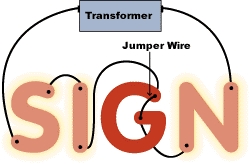
On a malfunctioning neon sign, one portion of the copy is normally dark or flickering dimly (Fig. 1). For example, if the letters read “SIGNSHOP” but only the “SHOP” is working, you’ll want to check all four letters in the “SIGN” portion for defective tubes. A bad neon tube doesn’t transmit current, so the faulty unit won’t show any signs of life. Sometimes a unit goes “flat.” This means that the internal gas pressure has dropped to the point where the tube can’t properly transmit current. The tube may illuminate dimly, but it affects the circuit in much the same way as a dead tube.
If you notice that the “S,” “I” and “N” are flickering dimly, there’s a good possibility that the non-flickering “G” unit is defective. Test this by using a piece of GTO wire to “jump-out” the unit (making a direct connection between the inlet and outlet wires) as per Fig. 2. Once the defective tube is bypassed, the other letters — “SIN”– should light up brightly with no flicker.
After turning off the power, remove the defective neon “G” unit and attach a jumper wire securely in its place using the tube supports. Because most servicemen are not tubesmiths equipped with portable neon plants, it’s going to be at least a couple of days before the job is finished. You must ensure that the bare ends of the jumper wire are in firm contact with the inlet and outlet wires. This normally means twisting the wires together and insulating the splices or pushing the ends firmly down inside the electrode housings. The bad news is that this temporary jumper will cause the sign to read “SI NSHOP” when illuminated, but the good news is that the transformer is spared the strain of a constantly shorting neon circuit until you return. In some cases (see “Sign Shorts”: Harry’s Cocktails,”), the shop owner may choose to turn off the sign until complete repairs are made.
Unfortunately, you’ll sometimes find that, even when all the neon units are good or the bad unit(s) have been jumped, the sign still flickers dimly. You immediately think “transformer,” but you’d better think again. A burned-out transformer frequently won’t provide adequate current even for the tubing to flicker. Inspect the transformer for any obvious signs of damage. If tar is leaking profusely from the casing seams, the transformer is probably defective.
Electrical Tests
The first electrical test is to check for proper supply voltage (normally 120V). Low voltage is the most common problem, and a 120V neon transformer requires a minimum of 108V across the primary input terminals. You should also check the mechanical grounding connection. This may consist of a green or bare wire (where plastic conduit or sheathed cable has been used), or a continuous line of metal conduit (EMT) from the T-box back to the electrical panel. Also check any mid-point grounding wires for proper attachment to the transformer posts.
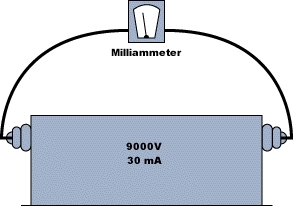
To test transformer output, shut off the power and disconnect both GTO leads from the transformer posts. The “short-circuit test” is performed with a portable milliammeter as shown in Fig. 3. With the power On, the reading should fall within a range of 27-33mA for 30mA transformers or 54-66mA for 60mA transformers. If the transformer does not test within this range, it is defective and must be replaced. Conversely, if the transformer does test properly, the problem must either be the GTO wiring or the transformer loading. Because they are actually composed of two 7500V transformers connected in series, 15,000V transformers must be tested one side at a time (Fig. 4).
The apparatus necessary to test GTO wire for concealed defects is hardly standard equipment for most signshops. Unlike lower voltage wiring for AC and DC circuits that can be field-tested using a pocket-size multimeter, testing high-voltage wiring requires more elaborate and expensive equipment. When I spoke with Allanson’s (Toronto, ON) Tony Efantes, he agreed that developing a more affordable, portable tester for GTO is a need that the industry should address. For the time being, however, visual inspection and “jump-testing” of GTO wiring are the only alternatives.
It’s easy to test the loops between individual neon units or channel letters, because you can jump-out the suspected wire(s) from the front of the sign. In most cases, however, you can’t jump-out the two ground return wires running back to the transformer box unless you’re prepared to drill holes through the wall and/or the channel letters for inserting your test wires. Unfortunately, most of the problems that develop in neon wiring occur in these ground return paths.
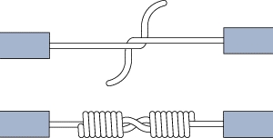
To inspect this wiring, turn off the power and detach the conduit from the transformer box. Then, unscrew the metal housing jacket from the glass insert at the opposite end of the conduit. Slide the conduit and metal housing jacket back to expose the GTO. Faulty GTO wiring is easy to identify, typically having melted or charred insulation with the copper core exposed. If the wire needs to be replaced, remove the strain relief connector, reattach the metal jacket and connect a new wire to the end of the old GTO by twisting the stripped ends together in-line (Fig. 5). Cover this splice with electrical tape to prevent snags when pulling.
Next, from the front of the sign, remove the neon tubing (with power Off). With your finger or a pair of needle-nose pliers, reach down into the electrode housing and grasp the spring connector to pull the GTO completely out of the conduit as the new wire is pulled through. After pulling the end of the new wire through the front of the electrode housing, disconnect the old GTO and attach a spring connector to the new wire. Push the wire back until the spring connector seats at the rear of the glass housing sleeve. Don’t forget to reattach the other end of the conduit securely to the transformer box when you reconnect the GTO to the transformer.
Relief or pain?
Although I appreciate the function of strain relief in electrical systems, these connectors can create more problems than they solve when used on high-voltage neon wiring with electrode housings. In addition to making the replacement of bad GTO wires difficult, the connectors can actually cause short circuits in some cases. This is because the connectors are made with an outer metal ring that is crimped with pliers for attachment to the GTO. If the installer crimps the connector too firmly, the metal crimp ring bites into the GTO’s insulation. High-voltage current arcs to this metal as soon as the sign is energized. Even when the crimp ring does not penetrate the GTO covering, dampness can cause the high-voltage current to arc to the metal.
These kinds of concealed shorts can drive a serviceman crazy, because he must remove conduits or perform extensive testing to locate them. In some cases, signs must be completely rewired because several strain relief connectors are shorting-out the system.
Another problem is that there seems to be considerable confusion regarding exactly where the strain relief should be located. The proper location is inside the housing’s metal jacket, just behind the inner glass sleeve. Some installers, however, apparently believe they should be inside the glass sleeve. Considering these shortcomings, I question the value of strain relief on high-voltage neon wiring. I’m not an electrical engineer, but I think it’s a mistake to assume that every priniciple applicable to lower voltage wiring should automatically be extended to neon wiring. At the very least, someone needs to develop a non-conductive method of strain relief. If you’re lucky, the installer thought those “little silver discs” included with his sign hardware were just spare parts and left them at the shop.
Transformer loading problems
Loading refers to the size and length of tubing in a particular neon circuit operated by a given transformer. Both overloading and underloading a transformer can cause failure. Overloaded transformers provide inadequate current for the length of tubing operated. This frequently causes the GTO insulation to break down and the wiring to short-out. It can also burn out the transformer. Underloaded transformers create excessive heat throughout the system. Both the tubing and transformer will typically “run hot,” leading to early failure. Because transformers are designed with an 80% load factor (80% of the short circuit current rating), the optimum load currents are as follows:
- 20mA transformers: 15.5-16.5mA
- 30mA transformers: 23-25mA
- 60mA transformers: 46-50mA
To test actual transformer loading, turn off the power and connect a milliammeter in series with the neon circuit and the transformer (Fig. 6). Turn on the power and observe the milliammeter reading. For a typical 30mA transformer, a low reading of 15mA indicates overloading, while a high reading of 29mA indicates underloading. If the transformer is overloaded or underloaded, you have the options of either installing a different transformer or altering the tube-loading arrangement. It’s a mistake to assume that the original installer necessarily observed proper loading requirements. Perhaps the original transformer has been replaced with the wrong size (ie, a 15,000V transformer replaced by a 12,000V unit). In cases of chronic transformer failure, always consider transformer loading as a potential cause. However, unpainted T-boxes can also radically shorten transformer life.
After you’ve completed testing and replaced any defective components, the sign should illuminate properly. Sometimes you may need to install bonding jumpers to curtail humming or buzzing caused by poor metal-to-metal contact throughout the system.
This may also be caused by loose conduit connectors or metal housing jackets that can simply be tightened to correct the problem. When the ground return path (either of the two secondary leads from the transformer) is more than 6 ft., bonding jumpers are required regardless of other factors.
Probably the best thing you can do for your customers is to let them know if they have a faulty or substandard installation. I’ve seen plenty of exposed GTO wires “snaking” through the spaces above storeroom ceilings. I’ve also seen “hot” GTO splices in crawl spaces and other notably combustible areas. If your client has a potential catastrophe lurking above his head, he’ll probably thank you for letting him know. The words “fire hazard” always seem to command attention. It may cost the owner some money to have a poor installation redone, but it’s a bargain compared to losing a building and maybe a business.
Editor’s Note: Thanks to Tony Efantes of Allanson (Toronto, ON), Henry Brown of Transco (West Columbia, SC) and Wayne Strattman, Neon Techniques columnist, who provided information for this article.
Secrets of Lead Generation
Boost your sales by generating more leads! In this light and lively webinar featuring Maggie Harlow, CEO of Signarama Louisville Downtown (Louisville, KY) and the “Business of Signs” columnist for Signs of the Times, learn the secrets of how leads are generated, where they come from and how you can cultivate better (not just more) leads.


Bulletins
Get the most important news and business ideas from Signs of the Times magazine's news bulletin.
-

 Women in Signs1 week ago
2026 Women in Signs Award Winners Anticipate Change
-

 Business Management2 weeks ago
Sign Company Investments of $10K, $50K and $100K
-
 Jameson Parker1 week ago
Signshop Layout, Part 3
-

 Women in Signs5 days ago
2026 Women in Signs: Heather Kincaid
-

 Women in Signs3 days ago
2026 Women in Signs: Cathie Bozman
-

 Benchmarks1 week ago
5 Signs Making Restaurants into Establishments
-

 Buzz Session3 days ago
Sign Companies on Their Debt-to-Income Ratios
-

 Women in Signs2 weeks ago
2026 Women in Signs: Judy Shano