AT THE 2006 International Sign Assn. (ISA) Signage and Graphics Symposium, speaker W.T. “Dub” Northcutt, president, Structural Technology Consultants Inc. (San Diego) told sign contractors they need to be aware of the footing size for the sign they’re estimating, fabricating or installing.
Saying the footing’s size affects the support pipe’s length and volume of concrete in a direct-burial application — or the volume of concrete and reinforcing steel in a spread-footing application — Dub underscored that either system has important variables. Both footings and sign poles can be substantially smaller if the soil values are obvious and certified, Dub said, adding that building owners, located on the same property as the sign, can help save money by supplying a soil report before a shop designs the sign and its foundation. The following article is based on the ISA presentation. Diagrams of the signs referenced are found at the bottom of the article.
Once a company and the associated graphic and sign designers have a general vision for a sign’s aesthetics, the designers and specifiers must consider the sign’s actual structural design and construction. This, of course, is based on the sign’s physical size and location, plus the designers must consider wind loads, soil conditions, footing types, sign-cabinet framing and the number of structural supports.
The client also must have access to a geotechnical report that details the site’s soil conditions, because it provides information that helps determine the design requirements and resulting footing depths. The following design illustrations are based on a typical, multiplex sign, where numerous companies would be represented. For these examples, the sign’s cabinet measures 25 ft. wide x 40 ft. high x 10 ft. deep. Its overall height is 60 ft. above grade.
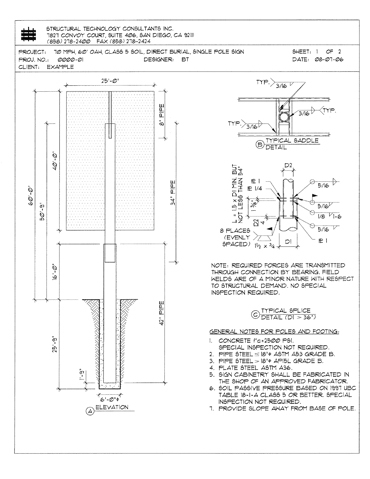
Sign 1 offers a good starting point for understanding the typical quantities and structural elements involved in structural sign design. In this example, a professional geotechnical engineer didn’t define the soil capacity and, therefore, the code-approved minimum values must be applied.
Advertisement
Using the tables found in the current, applicable code for worst-case, lateral-soil capacity, the required footing is a 6-ft.-diameter, 25-ft., 9-in.-deep cavity. This size footing requires approximately 500 cu. ft. of concrete. If a soil report had been obtained, chances are these sizes could be substantially reduced. Sign 2 shows the changes.
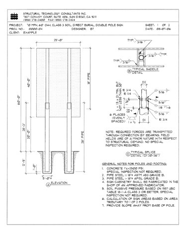
Sign 2’s structural design is based on twice the soil capacity of Sign 1, and many benefits spring from this detail. Note that the increased soil capacity is the only change — the above-grade sign is identical. Thus, the footing is still 6 ft. in diameter, but the depth requirement is now 17 ft. That detail changes the concrete requirement from 500 cu. ft. to 340 cu. ft., a 32% decrease in concrete fill.
Also, because the footing is almost 9 ft. less deep, the support post’s requirements have changed. The pipe’s first stage can now extend above the ground 9 ft. higher than Sign 1, and the upper, attached pipe is now substantially smaller (26-in. diameter compared to a 34-in. diameter). Also, because this pipe is now high enough to reach the top of the sign, only two pipes are required, instead of three, and only one splice is required, rather than two.
When comparing Signs 1 and 2, greater soil capacity clearly results in major design changes, and this leads to substantial construction cost savings.
Advertisement
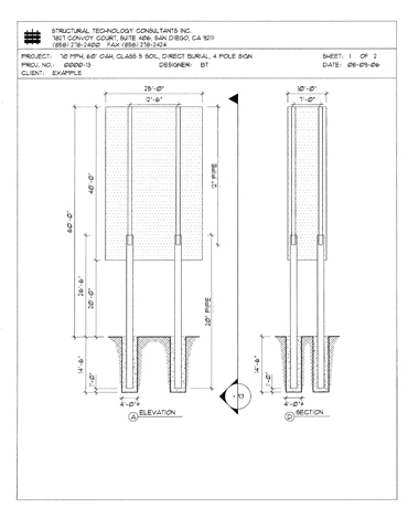
Study Signs 3 and 4. Sign 3 has the same soil capacity as Sign 1, but the post and footing (two instead of one) changes are definitely recognizable. In this case, the dual posts redistribute the load and, in doing so, create substantial benefits. The footing pipes now feature a 28-in. diameter rather than 42 in., and the upper pipe is 20 in. in diameter rather than 34 in. The footings are substantially smaller, so a third pipe isn’t required.
With two footings, Sign 3 now requires 600 cu. ft. of concrete, which is more than Sign 1, but other effects should be considered. The pipes are certainly smaller, and the footings’ depths are almost 7 ft. less, but there is still another benefit.
Sign 1 has a 25-ft.-wide-cabinet and one support, but notice the 12-ft. 6-in. cantilever in the middle of the cabinet, whereas Sign 3 has the same 25-ft. cabinet width, but two center supports. It has a 5-ft. cantilever. (STC defines the sign cabinet as a cantilever and the support pipe’s center line as the cantilever origin, thus a 25-ft. cabinet forms two, 12.5-ft. cantilevers, extending left and right.)
Sign 3’s design requires twice as many supports with its 5-ft. cantilevers, rather than the 12-ft. 6-in. cantilevers, so the cabinet members and supports can be noticeably smaller. Now let’s compare Signs 3 and 4. Because Sign 4 has better soil capacity, the specified footings are 6 ft. shallower, and the top support pipes are comparably smaller. Sign 3 requires 600 cu. ft. of concrete, and 4 requires 400 cu. ft. of concrete. Notice, too, that Sign 4’s 400-cu.-ft. concrete requirement exceeds that of Sign 2, at 340 cu. ft. , but 4 benefits from smaller-diameter support pipes, shallower footings and reduced cabinet-structure member sizes.
Advertisement
Signs 5 and 6 offer a unique design approach that can be helpful in solving atypical problems — below-grade, water-table levels, for example.
You’ll see that 5 and 6 have four vertical members (support pipes) and four footings, all smaller than those required in 3 and 4. You can apply this type of structure — spread footings — if deeper footings create problems, for example, if water-table levels are 10 to 15 ft. below grade. Also, although these drawings don’t show it, you can design and install 5 and 6 with spread footings.
Sign 7, designed with a cross-braced, truss system that provides major wind-load capacity, is very unique. The truss can be built with very small members. The sign is attached to a spread footing (rebar not shown) where the size is based on the overturning moment figures (overturning is the measurement of the bending moment at the pipe base), so soil pressure is not as critical.
Overall, the illustrated points prove that proper data and analysis, initiated at the design beginning, improves design decisions and, often, reduces costs.
Dub Northcutt is president of San Diego-based Structural Technology Consultants Inc. (STC), which provides practical solutions for the signage industry including: basic support systems, including poles, footings, base and cap plates, splices, connections and cabinet design upon request. It also provides Professional Liability (Errors and Omission) Insurance on every project. STC is licensed in AZ, CA, CO, FL, IA, LA, MI, NV, NM, NC, OH, OR, TX, and WA. He may be contacted at signengineer@stcsd.com. For related information and discussion, visit the “Fabrication and Installation” channel on www.signweb.com.


 Tip Sheet2 weeks ago
 Real Deal2 weeks ago
 Paula Fargo3 days ago
 Photo Gallery21 hours ago
 Signs of the Times4 days ago
 News1 week ago
 Special Report1 week ago
 News2 weeks ago