Channel letters are dimensional letters — available in numerous sizes — typically attached to a building’s facade. Many shops that sell channel letters order them from a wholesaler who, in turn, produces them to a customer’s specifications.
It once took a well-oiled team of designers, plus draft and craftspeople, to produce a single letter. Today, computerized artwork is used to produce a file that drives a computerized router, which cuts a letter’s backing and face.
Next, on a transfer strip, a sheet-metal specialist specifies where the coil stock or "return" of aluminum or mild steel must be notched, so it can be bent (in a curve, or right or left degree) by a hand-brake operator. In addition, the metal strip’s edges need to be flanged so the metal can provide a surface to which the backing and face can attach. This process takes nearly an hour for each letter. A large supplier can break up this process into stations so work can be performed simultaneously; marking, notching and bending steps need to be performed sequentially.
Because producing a letter is primarily a manual process, most shops tend to buy their own channel letters. Although most shops own a CNC router and brake, skilled craftspeople demand premium wages. A standard, 24-in. notched and shaped channel letter "return" takes a skilled craftsperson approximately 25 minutes to produce.
But what if all the manual processes were automated? |2258|’ Accu-Bend machine takes vectorized artwork and produces notched, flanged and bent metal-letter "returns" that conform perfectly to the router-cut face and back.
With the Accu-Bend, the only manual steps involve loading/unloading metal-coil stock material and final assembly of the finished letter. Using this machine, a standard, 24-in. channel letter takes approximately five minutes to produce.
We test-drove the Accu-Bend at Computerized Cutters’ Plano, TX-based facility and were impressed by the machine’s features and capabilities.
System specifications
The Accu-Bend comprises three component pieces: a computer station, material-feed table and bending unit. A true heavyweight, the machine consumes a 15 x 6-ft. space and weighs 1,500 pounds.
A dedicated, 115V 60Hz, 40Amp circuit is all you need to run the device. An air supply is needed to drive the bending mechanism, which requires 80-100psi at 3-4 CFM.
The brains of the unit, the computer console, is a standard, off-the-shelf, Windows-based PC housed in a protective cabinet. The preloaded software and operating system are configured when the machine arrives from the factory.
There are no factory options for the system; the computer system contains off-the-shelf components that users can easily upgrade. Computerized Cutters believes the primary use of the system is to drive the Accu-Bend; therefore, system configurations change routinely.
A power switch on the right side of the protective cabinet provides power to the cabinet. Once you switch on the power, simply open the front door and turn on the CPU. The computer connects to the feed table via a serial communications cable.
Next is the feed table (Fig. 1). Aluminum coils are placed atop a movable turntable that sits atop the feed-table cabinet. The feed table is motorized and thus keeps material from uncoiling. The table can accommodate up to 400 lbs. of material, and the Accu-Bend accepts material thickness up to 0.063 in. Material height ranges from 1-91/2 in.
The material must feed in a clockwise direction. Media guides are raised so the material can be threaded through the Accu-Bend. Approximately 2 in. of material should protrude through the bending station. At this point, a few loose coils of material should remain around the main coil. The table will lock the media in place to prevent it from "springing" onto the floor.
Accu-Bend station
The Accu-Bend station, which looks like a lab table with buttons and gauges, is logical and simple. The best way to describe the Accu-Bend is to follow the material’s path from the feed table to the finished-letter table.
Upon leaving the confines of the coil, the material may not be straight and true — metal tends to have a memory. To ensure it passes through the other stations in a straight line, the first station is the straightener assembly. A knob is used to adjust the straightening process. Keep in mind, the material can be as thin as 0.030 in. and as thick as 0.063 in.
Next, the feed-assembly station pushes the material through the other stations via a set of powered, rubber wheels. The pneumatic system controls a set of aluminum wheels, which pushes the material against these rollers when things have to get moving. Stepper motors control the rubber wheels for precise movements.
Because notches and bends must be precise, the machine needs to know the speed, position and direction in which the material is traveling. A feed-encoder assembly helps determine this information.
Now we come to the notching assembly (Fig. 2). The hydraulically operated notcher can produce 40
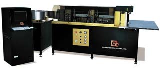


 Photo Gallery1 week ago
 Ask Signs of the Times2 weeks ago
 Paula Fargo1 week ago
 Real Deal5 days ago
 Photo Gallery1 week ago
 Women in Signs2 weeks ago
 Women in Signs2 weeks ago
 Projects5 days ago