Fluorescent lamps still rank as the most frequently used light source for illuminated signs, according to ST’s Electric State of the Industry Report (see ST, July 2008, page 87, Table 11a), which says they account for 37.6% of respondents’ illuminated-sign output, as well as the Lighting Survey (see ST, April 2008, page 104, Table 4), which says they account for 39.8%.
Fluorescent lamps require a ballast to start the lamp and control the operating current. For decades, only a few magnetic-ballast models existed, and all operated on the same principle. But, in the past five years, electronic ballasts (manufacturers tout their energy savings) have nearly replaced their magnetic counterparts.
I can’t explain both types’ properties, service and installation requirements in one column. I‘ll cover magnetic ballasts here.
Fluorescent lamps are often called “neon lights,” even if no neon gas is involved. For clarity, I’ll use the colloquial “neon” for cold-cathode tubes, while “fluorescent” substitutes for hot-filament cathode tubes, independent of color and gas fill.
Fluorescent-lamp principles
Advertisement
Fluorescent and argon/mercury-filled lamps share similar operating principles, except for their electrodes. Neon lamps, which bear cold, metal-shell electrodes, require high voltage to start and operate, but fluorescent lamps’ heated, filamentary electrodes often require a rather low starting and operating voltage. This is still higher than the common, 110V, U.S. line voltage, which means a fluorescent tube can’t be connected to the power line directly.
Before a fluorescent tube starts, the electrodes must be heated to approximately 1,400° F so they can release electrons into the gas. This is accomplished by running an electric current through the electrode, which comprises resistance wire. To make the current run through the filament, each electrode must have two connections. Consequently, the tube has four connections.
Contrastingly, a neon tube usually has two connections, because its electrodes don’t need to be heated to operate. Because generating a large amount of light is the fluorescent lamp’s main goal, its operating current is 300 to 800mA, or roughly 10 times a neon tube’s usual operating current. Once this operating current is running through the lamp, the lamp current maintains the electrodes’ operating temperature. This means “preheating” isn’t necessary after the lamp has started.
The fluorescent lamp and neon tube also share a so-called “falling characteristic,” where increasing operating current lowers the operating voltage. Thus, if a lamp with such a characteristic is connected to constant voltage (which is higher than the minimum starting voltage), the current would keep rising higher, to infinity, and destroy the lamp. So, power sources for neon tubes and fluorescent lamps must limit the current.
Consequently, a fluorescent lamp ballast must fulfill three, main tasks:
1. Prior to lamp start, it must preheat the electrodes by running enough current through the filament wires. Once the lamp operates, the heating current must be reduced or switched off to avoid overheating the electrodes.
Advertisement
2. The ballast must provide high voltage across the lamp to start the gas discharge between the electrodes once the electrodes have been heated.
3. It must provide a high enough voltage across the lamp, once the lamp has started, to sustain the gas discharge and, simultaneously, limit the operating current to a proper value for each lamp size.
Magnetic-ballast types
Inserting a resistor in series with a lamp would limit the current, but it would dissipate energy as heat. Alternating current permits the use of (almost) wattless, inductive resistance – or reactance – to limit the lamp current.
A basic inductor comprises a wire coil, which may be wound around a piece of metal. When an electrical current runs through a wire, it generates a magnetic field. Positioning the wire in concentric loops amplifies this field. Increasing the current in the loop increases the magnetic field, which applies a voltage opposite the current flow in the wire. In short, a coiled length of wire in a circuit (an inductor) opposes change in the current (or impedes it) flowing through it.
Magnetic ballasts are primarily inductors that limit (in electrical terminology, “choke”) the current. (Also, remember that inductors don’t work on direct current.) Here are three different versions of a magnetic ballast with their respective circuits and internal circuitry.
Advertisement
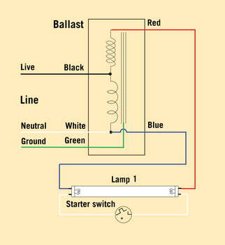
The simple ballast has a four-wire configuration with a starter switch. When power is applied, a small current heats up the thermal starter switch, which closes after a short time and runs a current supplied (and limited) by the choke action of the ballast’s magnetic inductance through the two electrodes (now connected in series). The closed switch cools and, when it opens, interrupts the current through the choke and filaments, which causes a high-voltage, magnetic induction pulse that’s applied across the lamp to open and ignite the gas discharge. The switch remains open; the current now flows through the lamp, and the filaments stop heating.
Magnetic reactance in the ballast limits the operating current, while the ballast’s transformer part steps up the line voltage to maintain enough voltage for the lamp to operate. If the lamp fails to initially start, the cycle is repeated, and the lamp flickers a few times while the starter switch heats and cools.
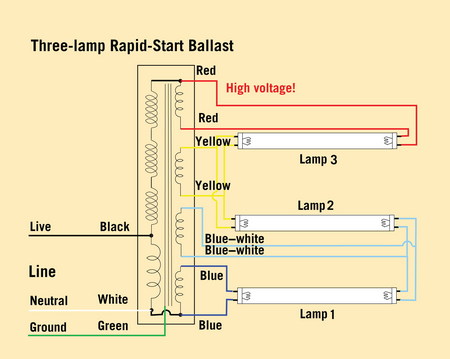
The rapid-start ballast avoids flickering and starts the lamp faster. This system doesn’t use a starter. The ballast simultaneously applies starting voltage across the lamp while heating the electrodes at first.
Constant voltage is applied across the tube as long as no lamp current flows. The filament heating reduces the voltage required to start the lamp until it’s lower than the applied voltage to start the lamp. Inductance in the ballast limits the current, which reduces the voltage across the lamp to the required, operating-voltage level.
After the lamp has started, the magnetic induction in the auxiliary secondary coils (used for heating) almost seizes so the heating current is drastically reduced once the lamp has started. The main secondary coil limits the current in the same way as a standard ballast. The lamp, which takes approximately a half to one second to start, doesn’t flicker. It also requires four wires for each lamp.
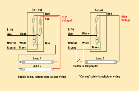
The instant-start ballast, in contrast to the normal, four-wire configuration, uses only two wires per lamp. The electrodes aren’t preheated. Instead, a high-voltage strike starts the discharge, as in a normal neon tube, which causes the lamp to start immediately when power is applied.
Thus, in the instant-start ballast, the lamp is started before the electrodes are brought to minimum operating temperature, and the electrodes are heated only during lamp operation by the lamp current itself. The ballast must initially supply high voltage (more than 1,000V, depending on the lamp type) to start the lamp, then low operating voltage at a limited current, without overheating the ballast.
U.S.-style, instant-start ballasts comprise a high-voltage transformer with a built-in series inductor to limit current. Some multiple-lamp models also have a power-factor-correcting capacitor across the input, which provides a higher power factor.
Forcing current through electrodes that aren’t heated during the lamp start causes them to act like normal, neon electrodes, but only on the small filamentary surface. This surface is too small to carry the current without being destroyed by sputtering. Consequently, each lamp start on an instant-start ballast partially destroys the electrode. Thus, to achieve an acceptable lamp lifetime, most manufacturers limit instant-start ballasts to applications with less than two to three switching cycles daily.
Servicing installations
Fluorescent-lamp failure can be tracked to the lamp, ballast, wiring or, eventually, the starter. Usually, the lamp’s electrode filaments have been burned (you can see black rings on the glass near the lamp ends). An electric-resistance meter must show continuity when connected to the two pins of each lamp end.
Assuming the lamp, incoming power and connnections in the lampholders are good (and not corroded, as they are in many outdoor signs), then the ballast might be faulty. Remember: Always observe safety rules when measuring energized equipment!
If a starter-type, magnetic-ballast installation fails, change the starter first. You can’t effectively test a starter onsite, and a starter costs only 50 cents. The connecting pins (which shouldn’t be corroded) must provide positive contact in the starter holder.
If the lamp still doesn’t work, check the ballast by removing the starter, with the lamp in place, and switching the lamp on. A voltmeter check will show if more than 110VAC are present across the contacts in the starter holder. If not, the ballast and/or the wiring is the problem.
Rapid-start ballasts (which often bear multiple lamp outputs) normally have pairs of the same color-coded wires. With a voltmeter, between the two wires of the same color, check if at least 6 to 12V are present when the ballast is switched on. (Warning: The wires can carry deadly voltage to ground, even if, between them, there is only low voltage! So, be careful!)
If all the wire pairs, lamps and holders pass this test, check if the ballast outputs high voltage by either measuring it with a high-voltage meter (with a 1kVAC range) between a red and a blue lead (check which color code goes to only one tube end in the manufacturer‘s wiring diagram). The reading should be roughly 120 to 200V for a one-lamp, low-wattage ballast and several hundred volts for a four- or six-lamp ballast. Some ballasts require the lamps to be inserted into the holders (so-called “cut-out” lampholders) to activate the high voltage.
Use equipment that can deal with high voltage exclusively to test rapid-start ballasts. I don’t recommend taking onsite, electrical measurements on instant-start ballasts because of voltage hazards, unless you have the proper training and equipment.
To safely and quickly test an instant-start ballast, take a short, 15W lamp (that’s definitely working) and connect it between each red and blue lead, then switch it on momentarily. If the ballast works, the lamp will light on every red wire. But, remember, this is a very quick test.
Humidity and high temperature impact outdoor sign cabinets. Thus, select the proper ballast type designed for each application and install it according to the manufacturer’s instructions. For example, some types require a horizontal, long axis and a direct mount onto metal to properly dissipate heat.
Avoid installing any electrical item on the bottom of a cabinet, because water will accumulate there and cause severe damage, even if there are drainholes.
Click here to read Fluorescent Ballasts, Part Two.


 Russell Toynes2 weeks ago
 Maggie Harlow6 days ago
 Electric Signs1 week ago
 Mark Kissling1 week ago
 Dale Salamacha1 week ago
 Signs of the Times2 weeks ago
 Product Buying + Technology2 days ago
 News1 week ago